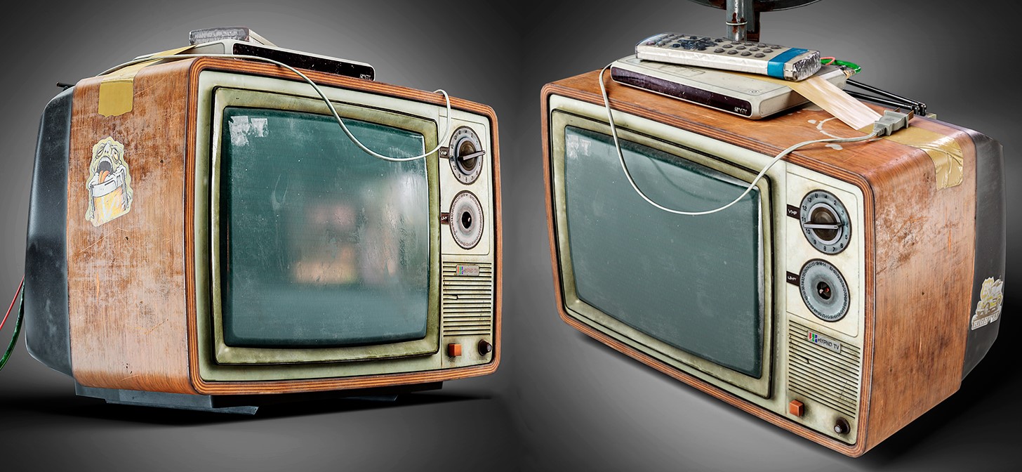
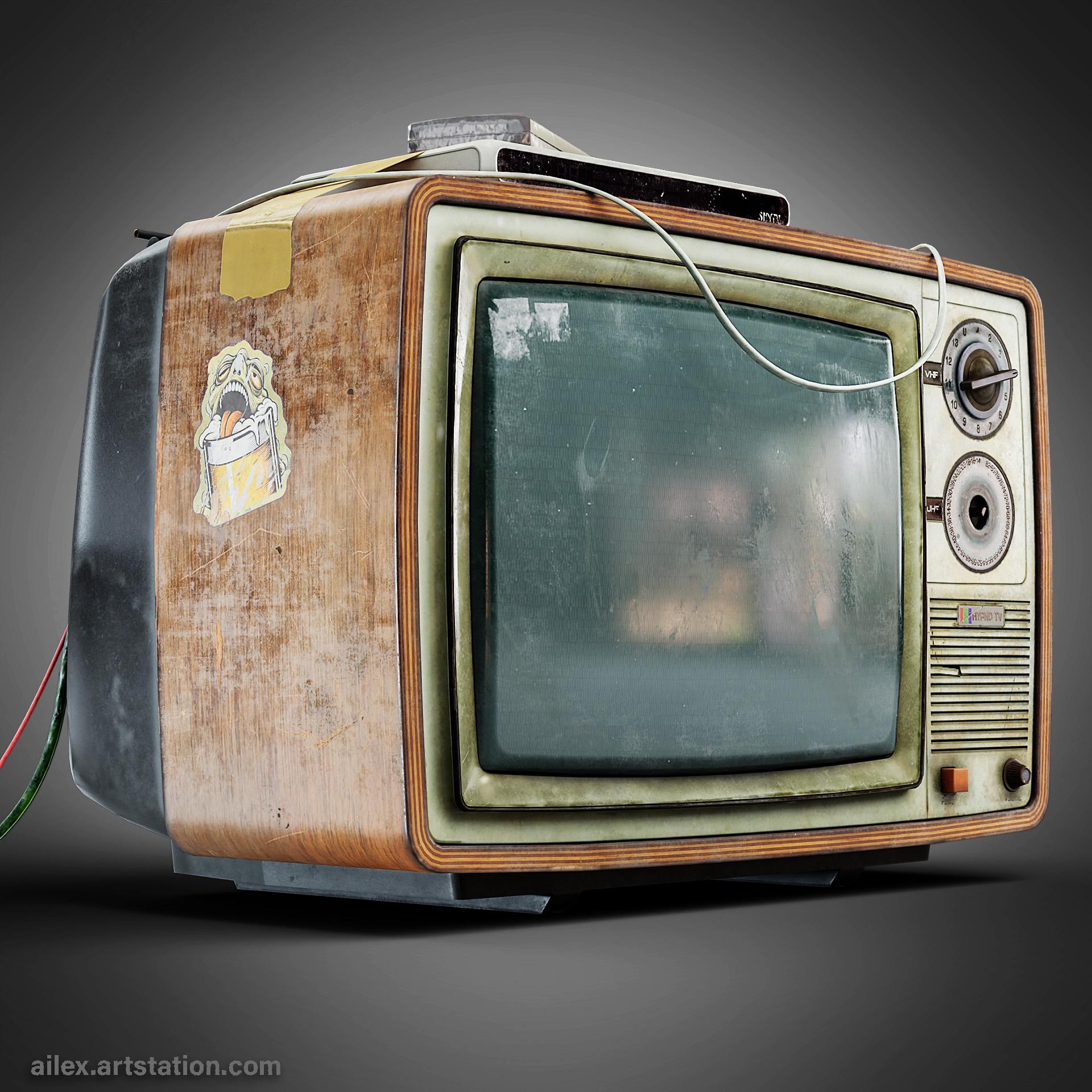
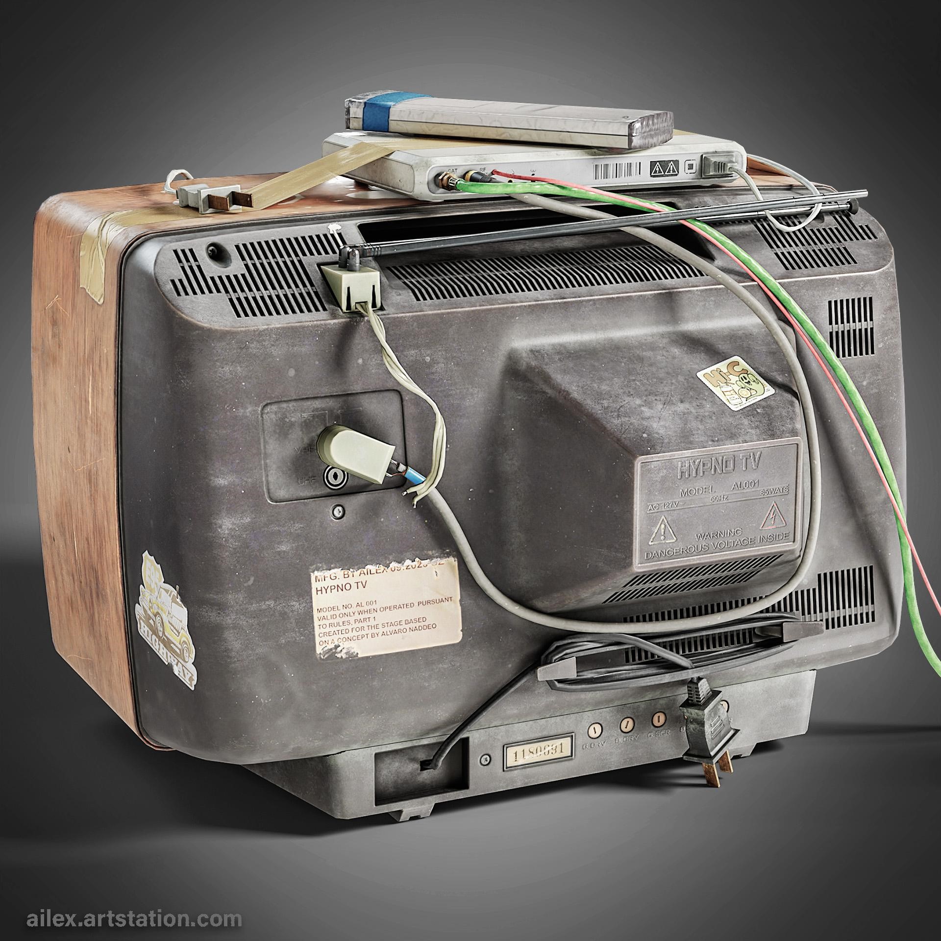
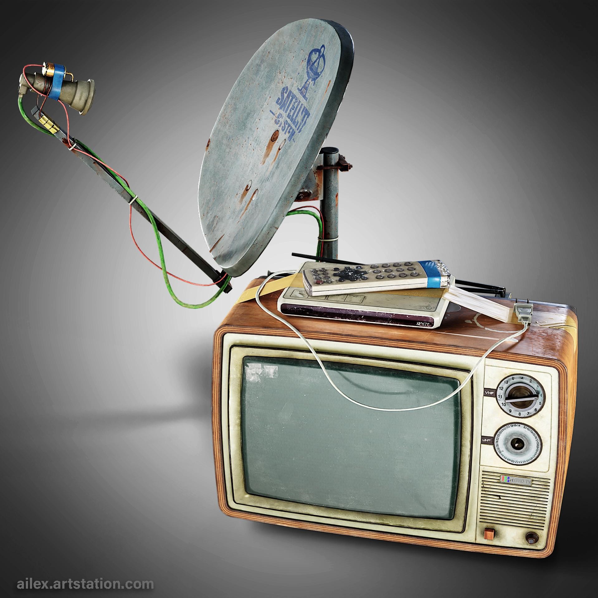
Behind the Scenes: Portable TV
INTRODUCTION
Hello, my name is Aleksandr Kochkurkin. I have been fascinated by the world of 3D for a long time, but life circumstances led me down a different path. In the past, if I may say so, I was a programmer of automation systems. Now, I have been learning 3D on my own for more than 2 years and plan to work in the video game industry.
INSPIRATION
This work is part of a larger project: I intend to reproduce in 3D the work of the artist Alvaro Naddeo, author of unusual paintings. According to his concept, I made a block-out of all the elements.
PROCESS
I did the modeling and UV in Blender3D. I didn’t use anything special for modeling—just a standard high-poly to low-poly bake pipeline.
References
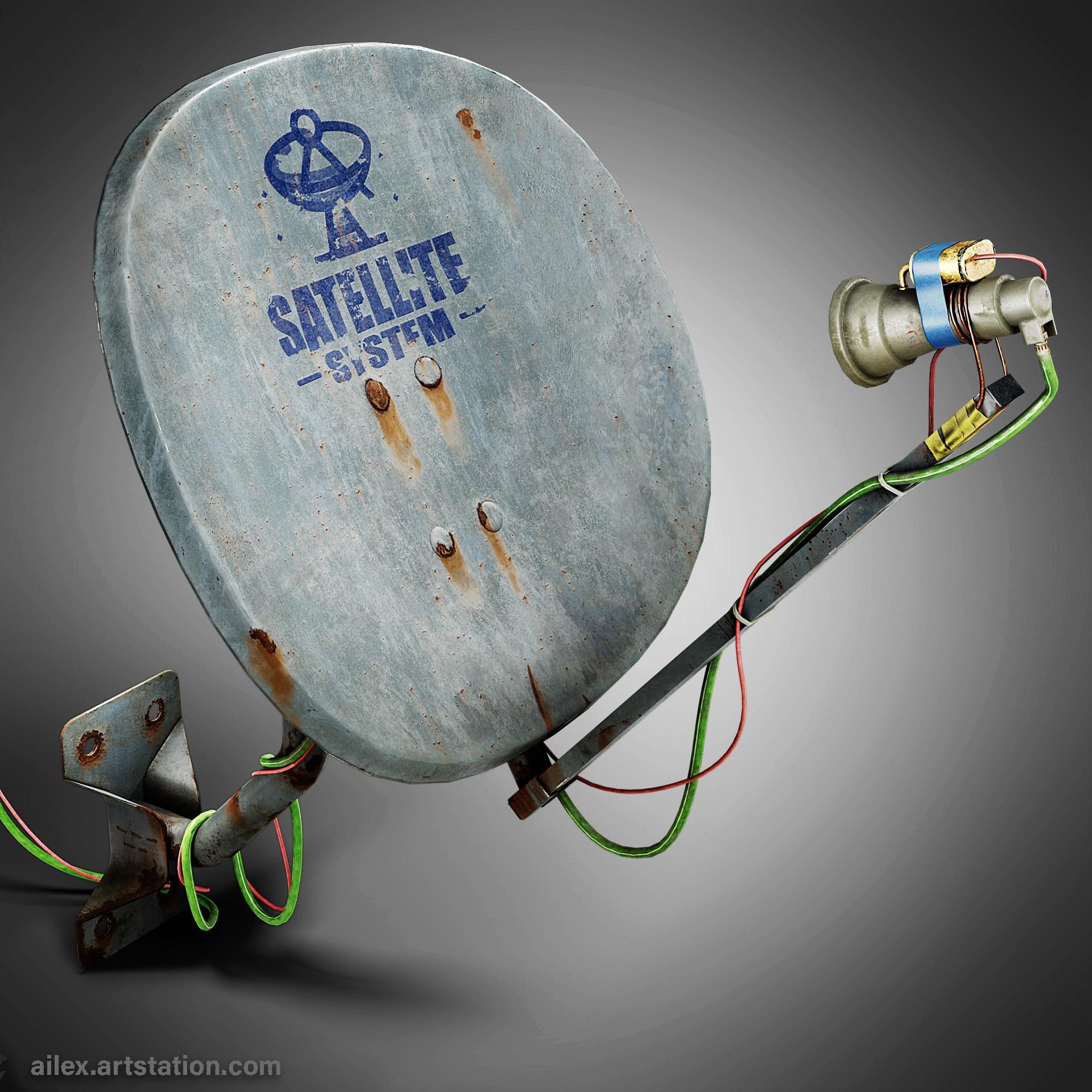
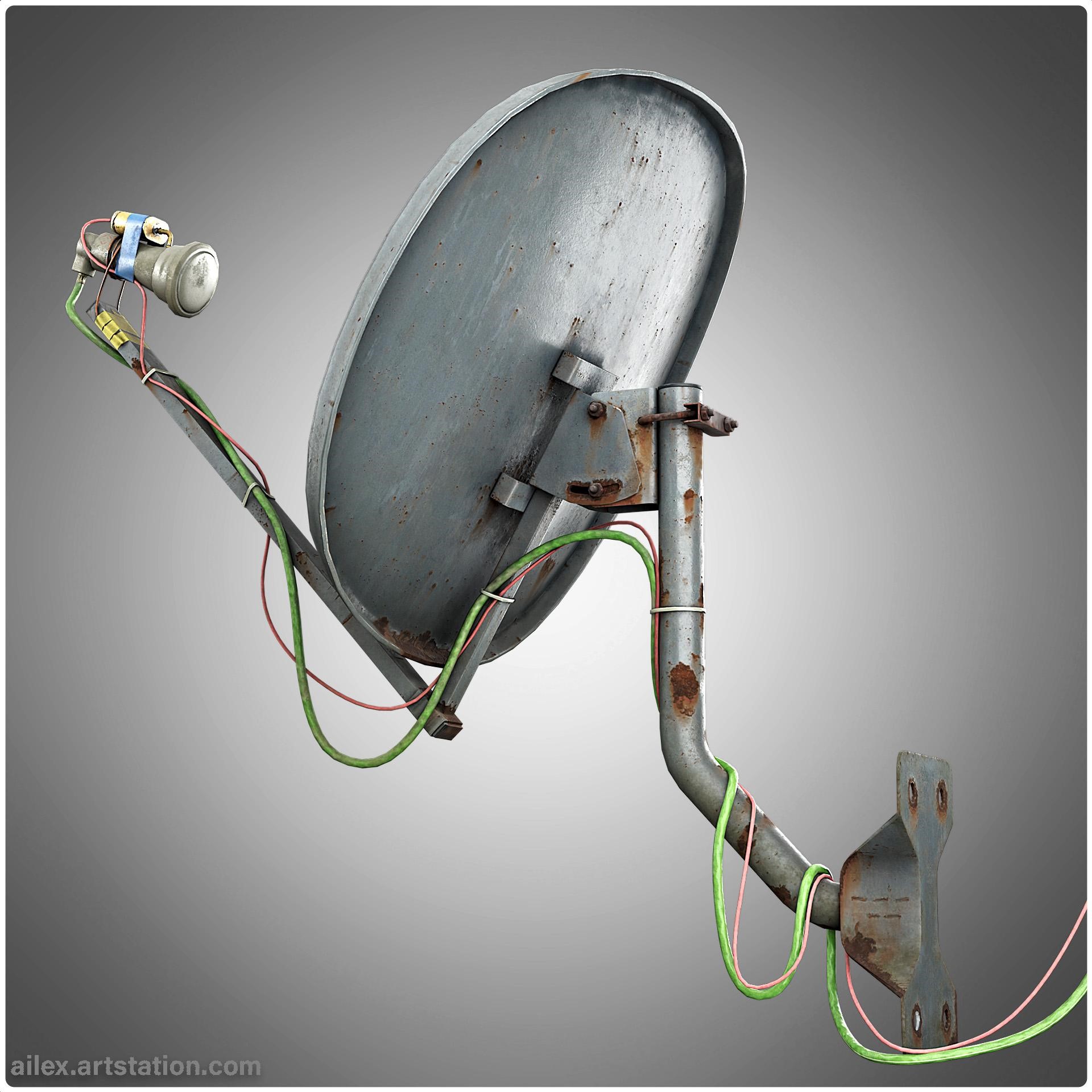
To create a television with an antenna, I did not use any specific references to real objects. It is a collective image close to the concept. Basically, I took shapes and proportions from real objects. I added the missing satellite receiver to the concept.
Modeling
First, I created a high-poly model. At this stage, I finally decided on the dimensions, shape and detailing. The modeling was done under subdivision, which came in handy later when I had to adjust the size of the chamfer after baking.
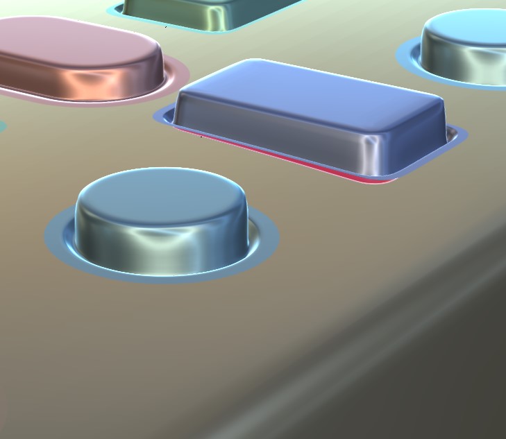
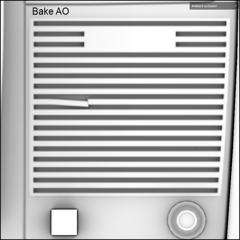
Many elements of the detailing were created using floating geometry (floating geometry is often used to add detail that would be difficult or impossible to create with the base geometry of the model). This makes it easier to get clean shading on complex details. For example, I created all the grids on the TV, the buttons on the remote control and satellite receiver, and the connectors on the receiver. This method can lead to some errors when baking the ambient occlusion map, but I will show you how to fix it.
Once the high-poly model is complete, you can move on to the low-poly model. This is basically removing the subdivision and reducing the number of vertices. Since this is a personal project, I just made as few vertices as possible with a good look.
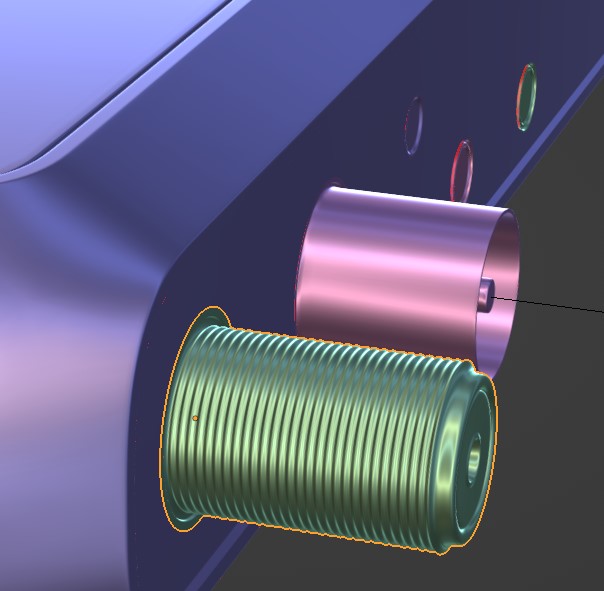
I also want to tell you how I make different wires; you can not only make wires but, for example, rope with tips. For this, I use the modifier Array. I create three elements of the wire: the beginning, the middle, and the end. If we talk about the power connection wire, the initial one can be the same as the middle one, it will be needed to bake on its ambient occlusion from the device to which it is connected. The middle one will be repeatable and set the length of the wire. The last one will be a plug, for example. I add the modifier “Array” to the middle element, it will be the main element.
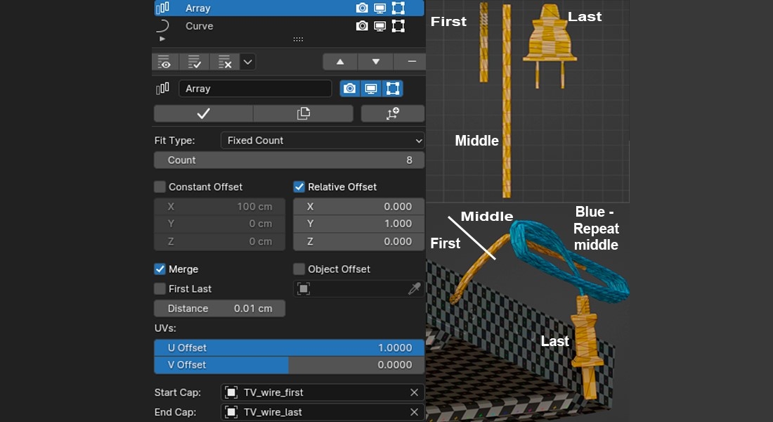
In the modifier on the “Cups” tab, the first and last elements are set. Next, I use the “Curve” modifier to set the shape and direction of the wire.
UV
I often do UV unwrapping in conjunction with a low-poly model. In this project, my goal is to have a texel density of at least 10px/cm. At this stage, I think about which elements will have overlaps (if they make sense and are possible). I straighten all shells that can be straightened without a lot of stretching, which saves space on the texture and allows you to get a higher texel density with a smaller texture and avoid aliasing. When working with UV, I use the TexTools add-on to help with unwrapping. After finishing low-poly modeling and unwrapping parts of the object, I start packing by using the UVpackmaster addon.
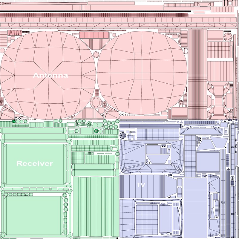
As a result, I got 5 sets of textures:
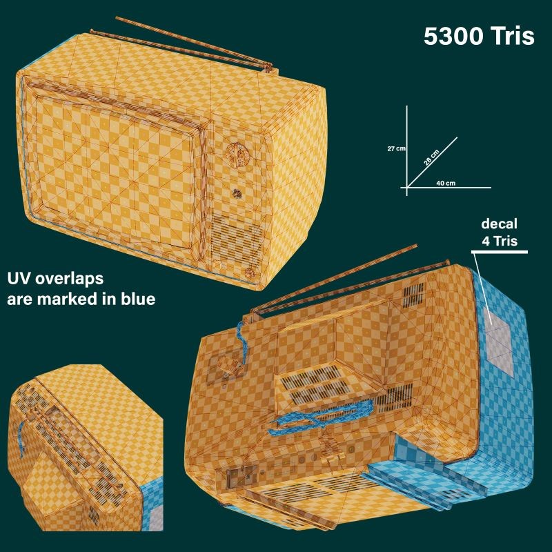
- TV – 1024×1204 px;
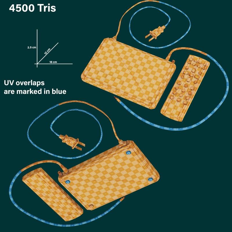
- Satellite receiver with remote control – 512×512 px;
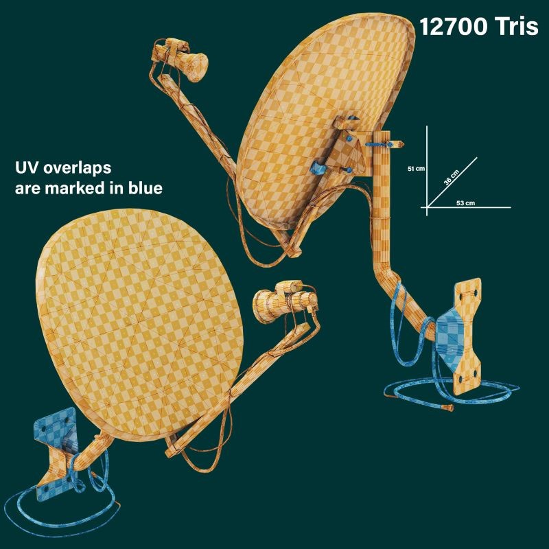
- Satellite antenna – 1024×512 px;
- Translucent tape and cover for remote control – 256×256 px;
- Decal for overlap dilution on the left side of the TV – 128×128 px.
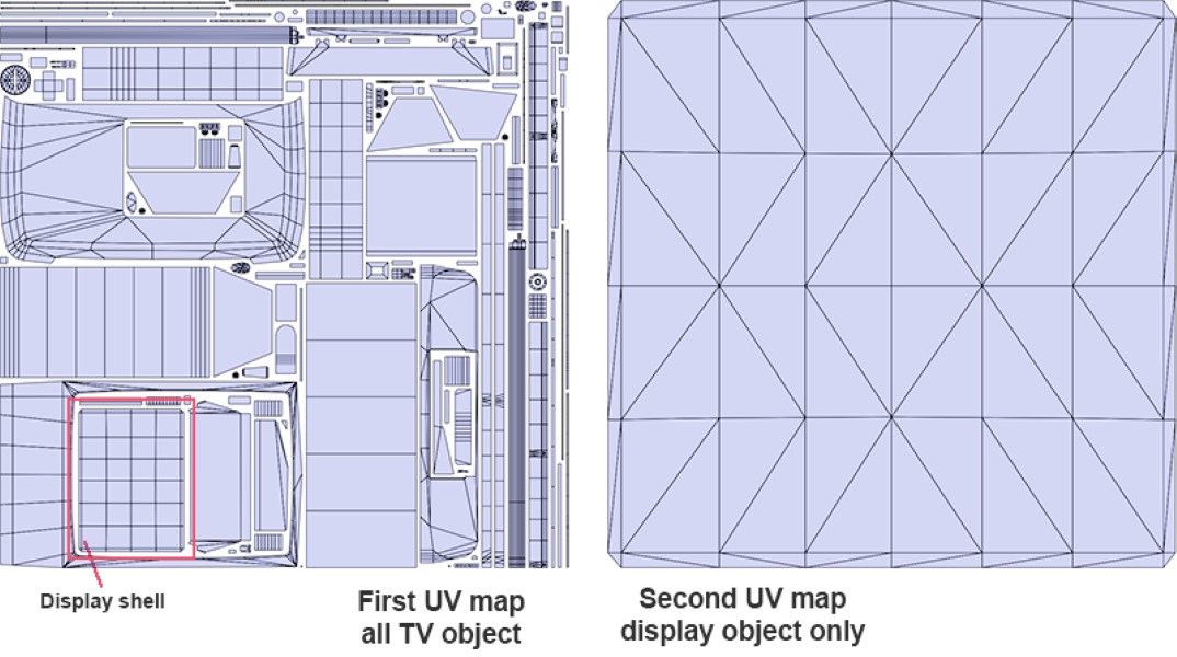
The image shows the UV-maps of only the first three objects.
Before exporting the model for further work, I transferred all overlays from the main UV space to the neighboring one with UV coordinates 1…2.
Baking
I baked in Marmoset Toolbag and Substance Painter. Before exporting the models from Blender 3D, I named them according to the groups that will interact during baking and added the suffixes _high and _low. For example: Box_high, Box_high.001, Box_high.002 – composite high-poly model that will be baked on Box_low. I assigned materials to low-poly models for further identification during baking, texturing, etc, as only the name of the material is important. The number of materials is equal to the number of UV sets. To create a color ID map for use in texturing, you can assign materials to high-poly models and individual polygons on them. It does not matter the name of the materials and their number, and you can set the necessary color.
In the Marmoset Toolbag, I baked maps: Normals, Normals(Object) aka WorldSpaceNormal, Curvature, and Ambient Occlusion. The rest of the maps were baked in Substance Painter with normal averaging disabled. I fix problems with convex/concave objects baked onto flat surfaces in the low-poly model in the Marmoset Toolbag with the “Skew” tool if it’s a simple flat geometry and there are no close seams. If the geometry is complex and there are close seams, I add additional edge loops on a low-poly model that has been duplicated specifically for baking.
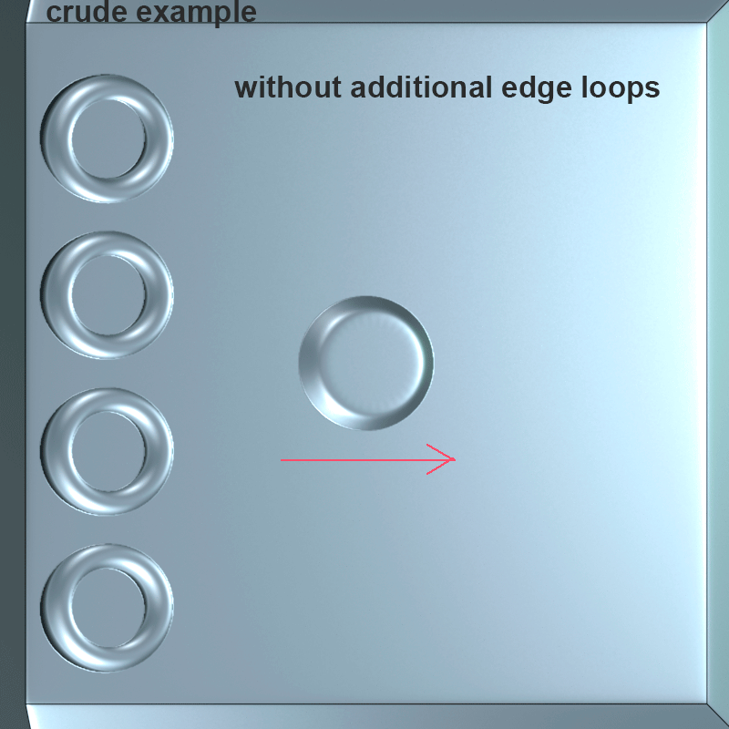
The new loops should be placed around where the detail will be baked, taking care not to mess up the shading of the low-poly model. I don’t like the common method of using Photoshop.
Texturing
Texturing was mostly the usual—generative masks, hand-drawn masks, and hand painting. But I’ll tell you a few of my own techniques that I used. I also used resources from texture.com.
Correction AO map
After baking, ambient occlusion can form defects around the floaters. And this can spoil both the appearance and the operation of some generators. To correct baked AO (not necessarily from floaters defect but also from other problems of baking) you can manually do so in both Photoshop and Substance Painter. It is more convenient for me to work in Substance Painter, I will tell you how to do it. First in “Texture set Settings” you need to add the channel “Ambient occlusion” and change the setting “Ambient occlusion mixing” to “Replace.” In the “Layers” panel, I create a folder/group, add a fill layer to the folder, and insert a baked AO map into the AO channel. In “Layers,” I switch to the “Ambient occlusion” channel and set the folder to “Replace” blend mode.
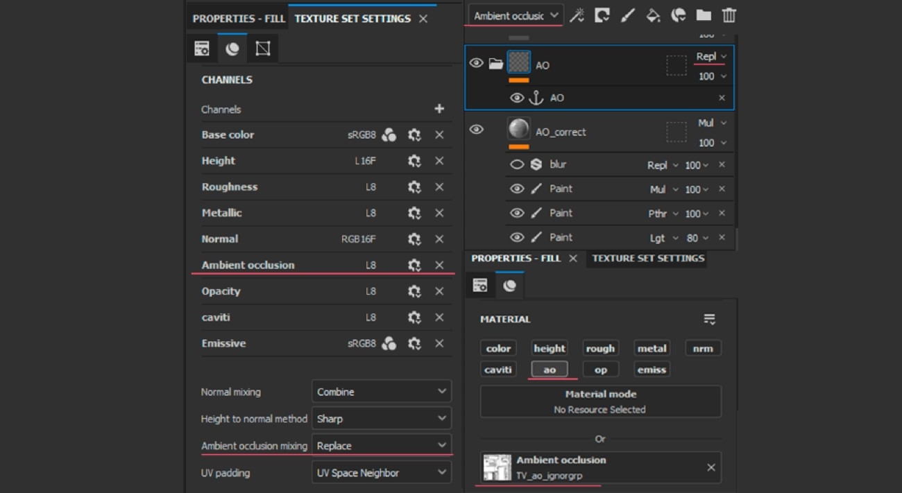
In the viewport I also switch to the “Ambient occlusion” channel and the model should show AO. Now, I add the “Paint” effect with the desired blend mode to the fill layer and correct all defects on the AO map with a brush or stamp.
I should add that this is not a very convenient way if you use many generators, because you have to remember to manually specify your new corrected ambient occlusion map for the generators. But at the same time, this way allows you to quickly make changes to the ambient occlusion map.
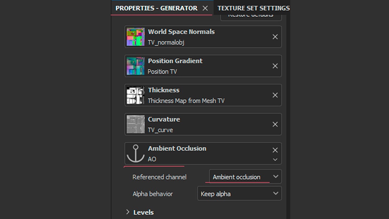
To specify a different AO map for the generator to use, you need to add “Anchor point” to the folder/group with the corrected map and select it manually in the generator properties in the “Image input” section.
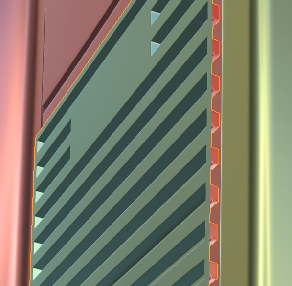
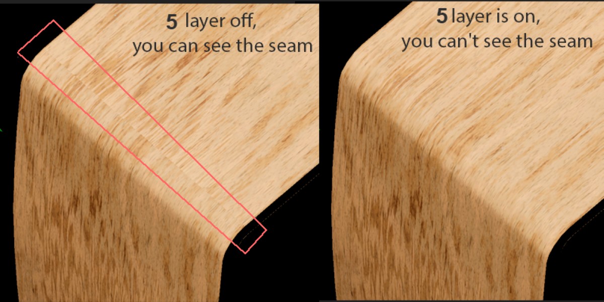
Wood texture & Overlap correction
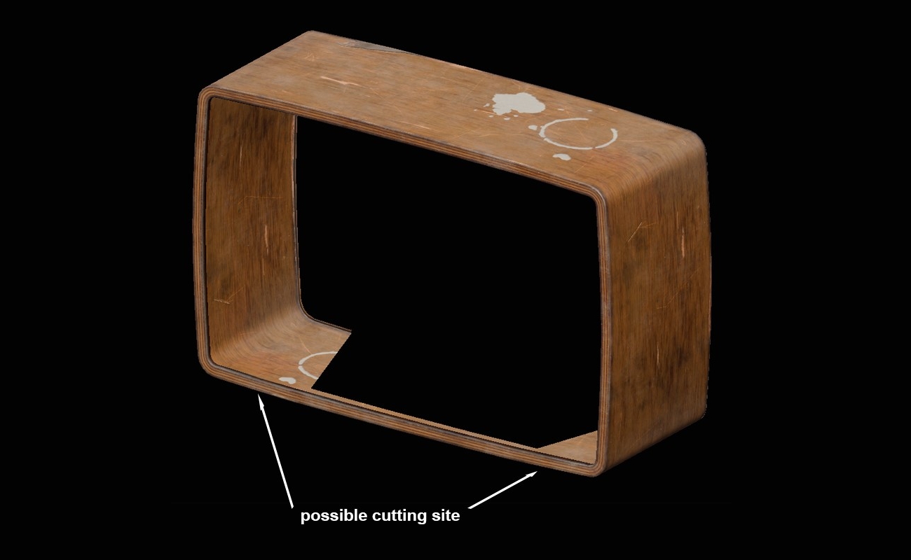
In my work, I was still using overlaps, and that adds some complexity and limitations to the texturing. I’ll give you an example of a TV. A very large overlap on the plywood box. If you look closely, you can see that the box looks solid without being cut into pieces. A real plywood box would have been cut into pieces. I made this simplification because the bottom and left wall are projected onto the top and right wall on the texture, and the cut would have been at the top.
Another difficulty with the overlap is the wood grain on the seams. I had to blend the patterns on the top so that the pattern on the left and right would not break off and form a seam at the overlap. I will show you my way of overlapping textures with a directional pattern. This is most suitable for wood textures, and in this case to fix the seam from the overlap.
I create a group/folder (1) and add to it a fill layer with a texture, you can mix several layers with each other (it is important not to use generators and other methods tied to the UV unwrap of the object, as it will break the further projection and you will see your UV unwrap on the object). Leave the projection mode of these layers at UV. Next, I set the group/folder’s blends to “disable” for all channels (2). Next I add an “Anchor point” to the group/folder (3). On top of the layer stack you can now add fill layers with masks onto which your texture will be projected. On certain areas in a certain direction in different projection modes (triplanar, planar, etc.).
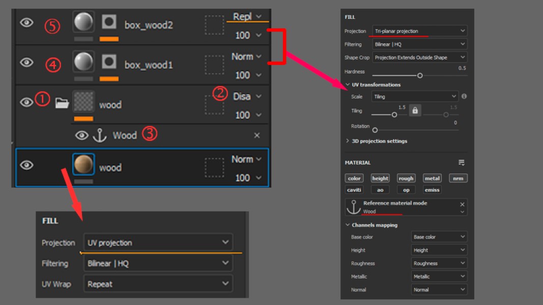
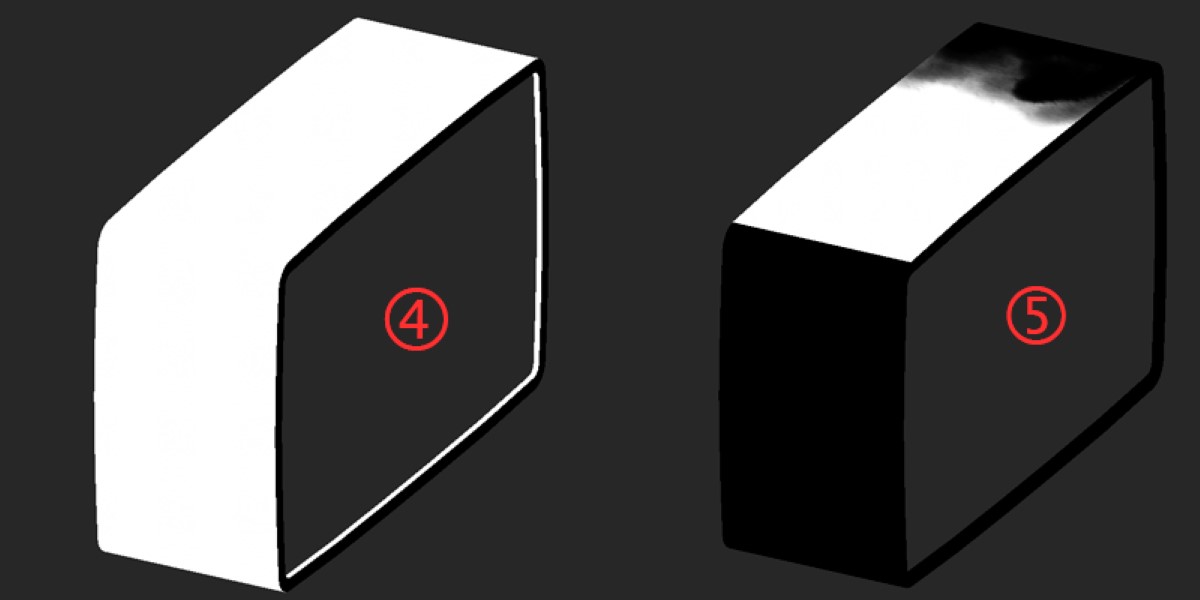
In my case, both layers are triplanar projected. The first layer (4) has a mask that highlights the projection points I need. The second layer (5) has a mask where I need to dilute the texture and hide the seam.
In the second layer, the texture is rotated on the vertical axis, its position is chosen so that its pattern continues smoothly, and a mask is manually drawn to hide the transition.
And as I wrote before – I always use this approach when projecting wood, because it always has a different pattern direction, depending on the complexity of the wood object. This approach allows you to change texture parameters in one place within a group/folder.
Otherwise, texturing was the usual – generative masks, hand-drawn masks, and hand painting.
Lighting & Rendering
The rendering was done with a regular three point light with additional sources to highlight interesting places and add highlights. Lighting is a difficult subject for me, every time I want to light my work it’s like the first time.
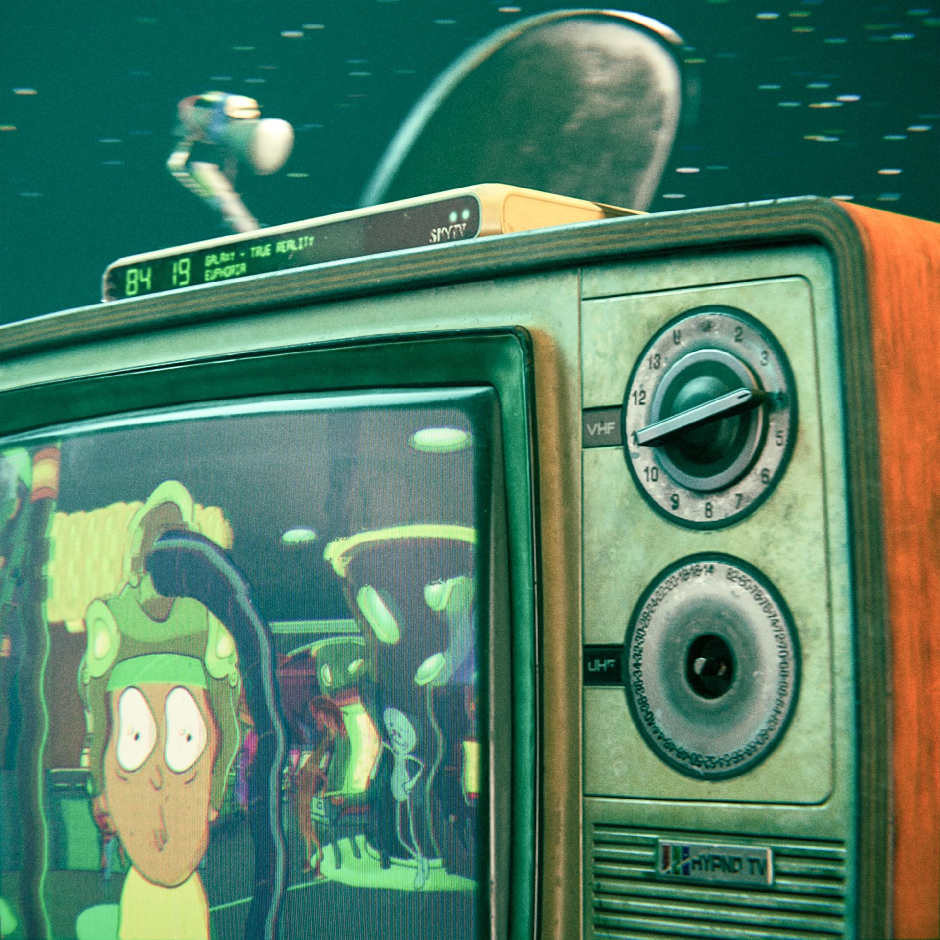
To render the TV with the screen and picture on, I added an emissive channel to the textures and made the screen glow white.
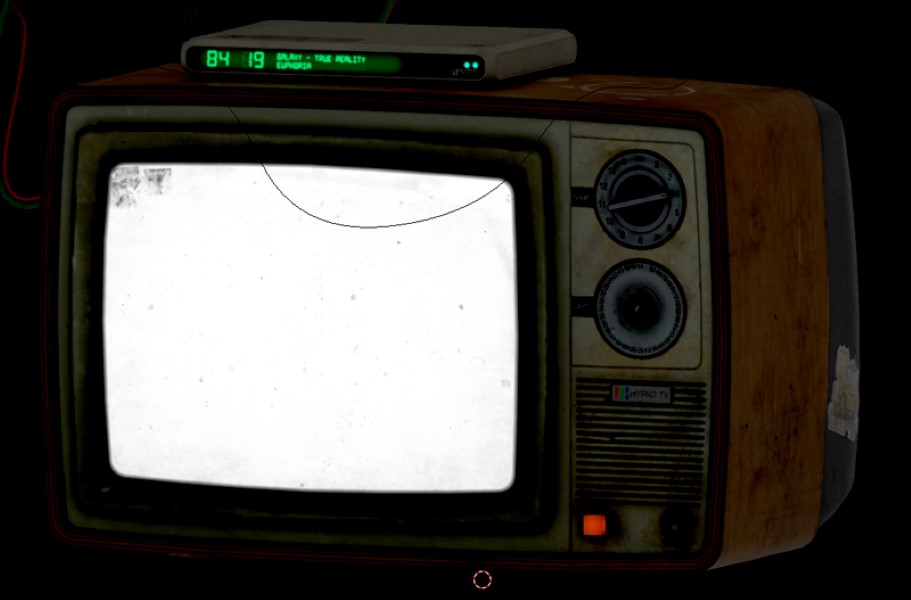
For the display object I added a second UV channel and made the display sweep over the entire UV space.
Then in the shader I mixed emissive from the main texture and the prepared image for the second UV channel to exclude the black frame around the display, here emissive on the screen plays the role of a mask. Blend mode “Multiply”.
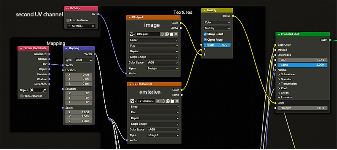
The second UV channel on the display allowed more flexibility in controlling the texel for the image so as not to lose clarity.
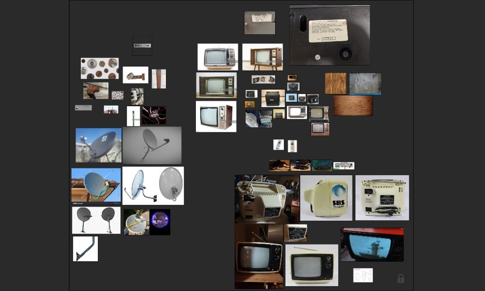
And that was all! Below are the final renders.
RENDER : Portable TV
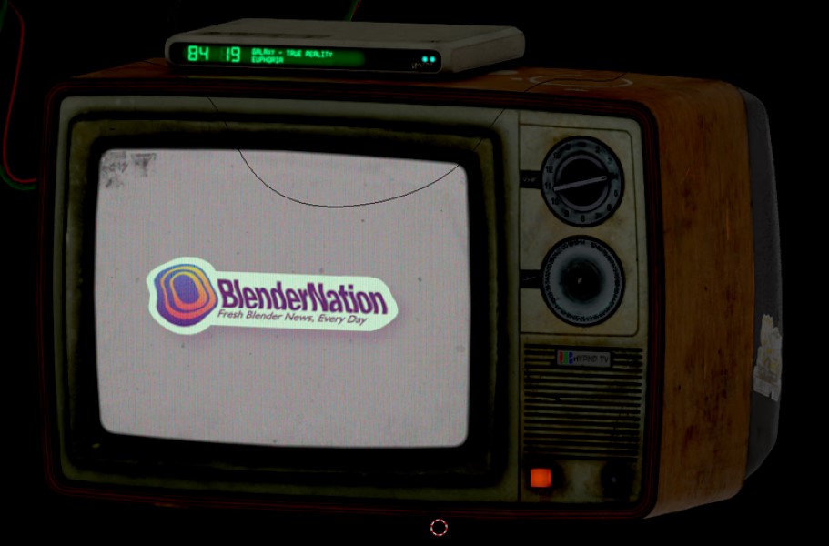
Thanks to BlenderNation for the opportunity to publish this article. This is my first public article. I hope it will be useful to at least one person.
Thanks for taking the time to read it!
About the Artist
Aleksandr Kochkurkin is a 3D artist who looks for something new for himself in 3D everyday.
Tutorial de esto?? muy bueno !!!