
Behind the Scenes: Cute Medieval Environments, Pt. 2
Hi, I’m Carlos Cavalcante. This is Part 2 of my three-part tutorial on how to create a cute medieval house. You can find Part 1 here.
6. Extra Details and Curve + Array Modifiers
For the roofbeam details, we can just take one of the curved planks we created before and then duplicate and rotate to arrange them nicely.
Then add the supporting loops and add the subdivision modifier to get that nice roundness!

If you want to iterate the thickness of your props, you can go to Edit mode, then select everything (A) and use the Shrink/Fatten (ALT+S) to move all the faces along their normals and “inflate/deflate” your mesh. This is another feature that I use A LOT! You can also try ALT+S+S and see how it works. ;)

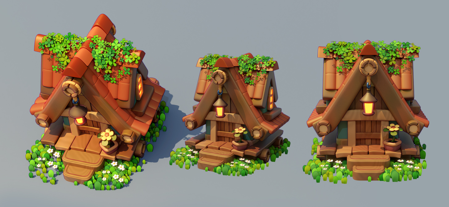
For the rope details, I created a simple rope tile using a subdivided rectangle. This tile is going to be replicated along a Bezier Curve, so we can create any rope details we want in a flexible way.
In Object mode, press SHIFT+A and insert a new curve. In this case, I’ll use the circle curve.
Make sure your rope tile is perfectly aligned with the curve center. For that, you can shift select the tile first then the curve second (make sure the curve has the yellow selection outline and the rope tile has the orange one), then press SHIFT+S and move around the Snap menu to the option Selection to Active
Also, make sure that both your tile and curve have the uniform scale 1,1,1 and rotation 0,0,0 by pressing CTRL+A and applying scale and rotation.

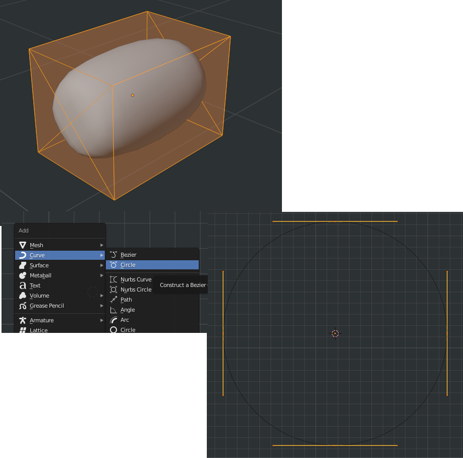
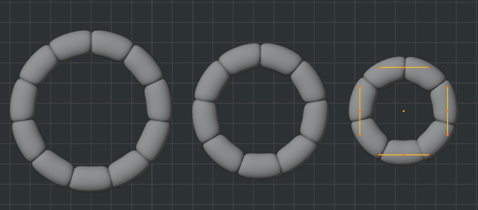
Select your rope tile, add an Array modifier, change the Fit Type to Curve and select the circle curve we just created. Play around with the offset to get the result you’re looking for.
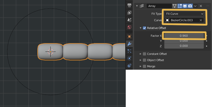
After that we add a Curve modifier and again we assign our circle curve object.
In Edit mode you can select your curve and play around with the mean radius to get different
thickness results (default value is 1). This panel is located in the Item tab (N).
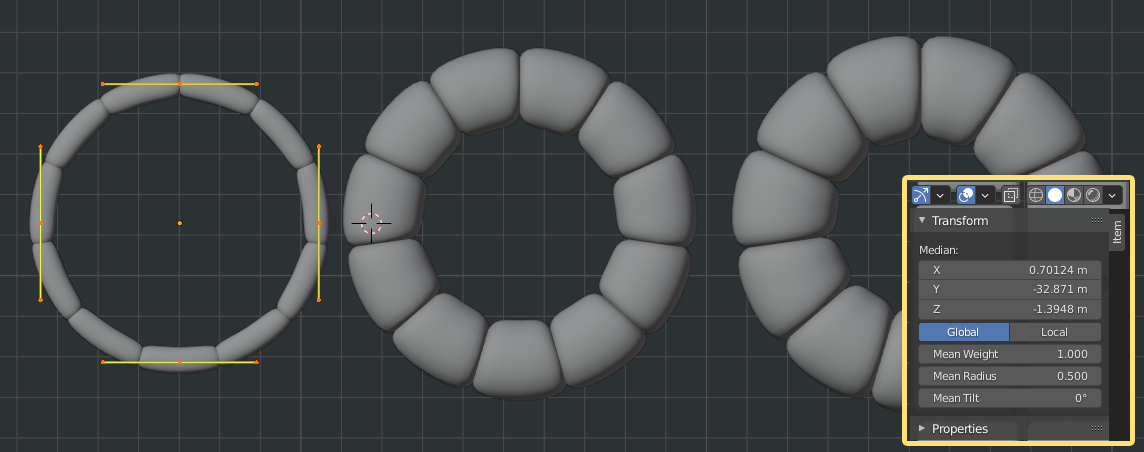
In Edit mode you can also scale down/up your curve and the array+curve modifiers are going
to rearrange the rope tiles quite nicely. You can even change the rope’s shape completely.
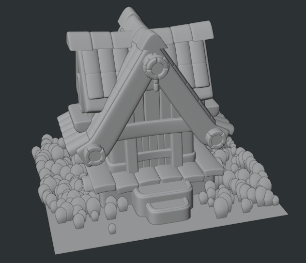
7. Nature Scattering
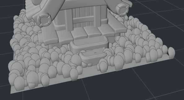
Let’s start scattering grass around our house now! When I created this piece, I was using Hair Emission for such a task, but nowadays I use the amazing Geometry Nodes for scattering objects.
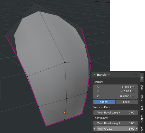
First, you create a grass blade object using a rectangle plane, subdivided in 3 loops, and then bent a bit towards the top part.
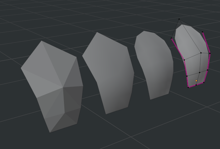
Since we are going to scatter this object a lot, we will keep the subdivision surface level to 1 for this object.
Also, set the side and bottom edges’ Mean Crease to 1.00.
Make sure that your origin point (pivot) is in a good place. If not, you can simply go into Edit mode and move your entire grass tile around to position it according to the origin point.

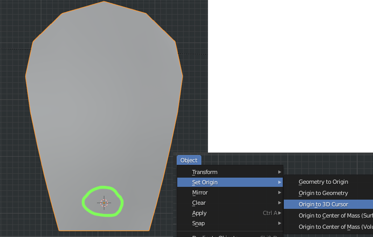
Or you can select one edge or vertex that has a good position for your origin, then press SHIFT+S and Cursor to Selected; after that, go into Object Mode, select Object>Set Origin>Origin to 3D Cursor in the top menu.
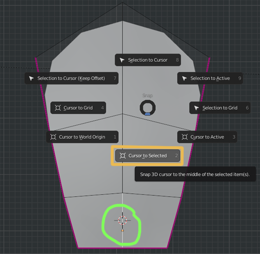
Try to avoid placing your origin at the very bottom edge of the object, we want the grass to be a bit inside the ground to make sure it feels physically there and to avoid some floating grass blades after the scatter.
And as always, make sure your scale and rotation are applied or you’ll see some weird results!
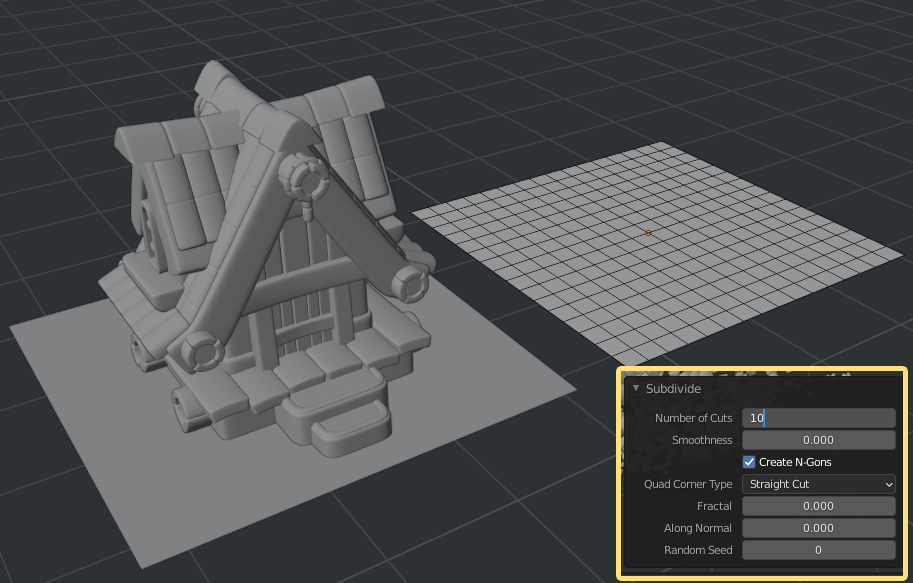
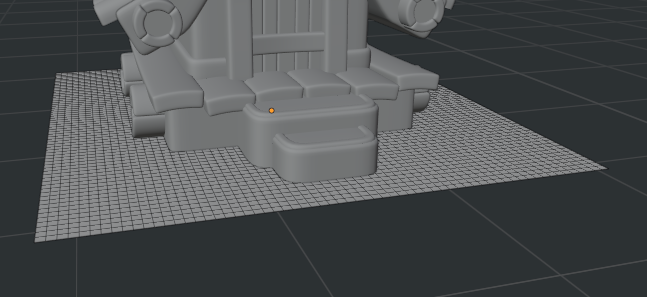
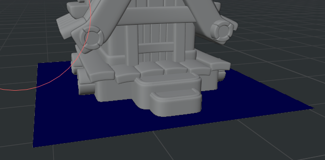
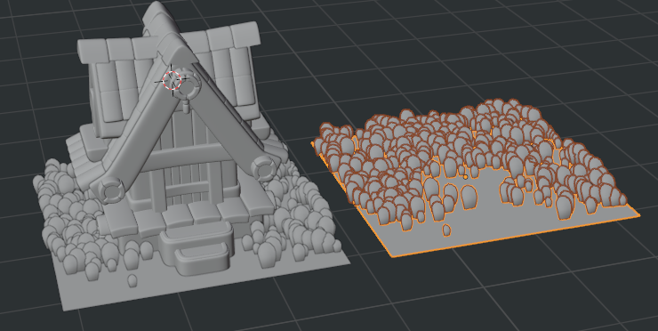
Now let’s create a plane that fits well as a base for your house and for our grass object to be scattered around. Subdivide it about 10 times (in Edit mode, select the whole plane, press W then Subdivide)—you can select the number of subdivisions in the context menu that’ll appear on the bottom left part of your viewport.
Make sure the plane scale and rotation are applied (1,1,1, / 0,0,0).
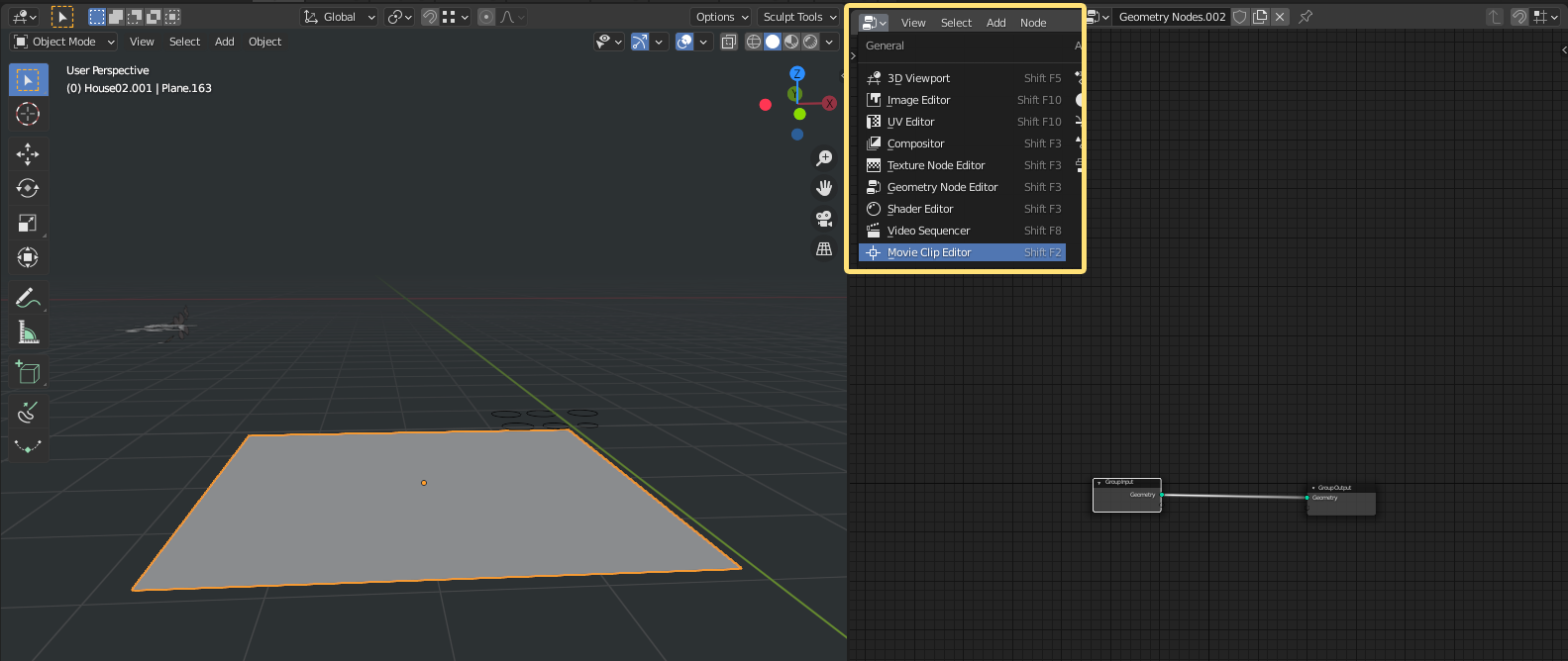
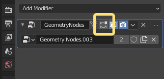
Split your screen and on the top left part of your new work area, select the Geometry Node Editor
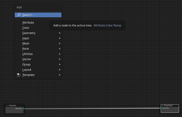
With your ground plane selected, press the create new button, in the top part of the Geonodes editor. This is what you’ll see by default: a group input and output nodes (never delete those) connected by a noodle (is that the official name? :D).
If you press SHIFT+A in the editor, you’ll see the Add popup, where you can also search for specific nodes.
So, separate your output and input nodes a bit, make some room for the node structure we’re going to create.
First, you’ll add a Join Geometry node. Just create and drop the node on top of the noodle and it’ll automatically connect.
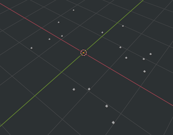
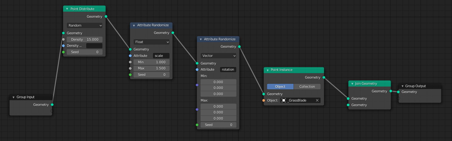
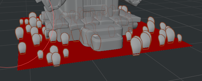
After that, add a Point Distribute, when you do it, you’ll notice that your plane object vanished and got replaced by some dots. These dots are not objects, these are just things being distributed on your plane geometry. Now we need to tell Blender what to distribute instead of these dots.
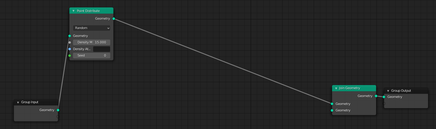
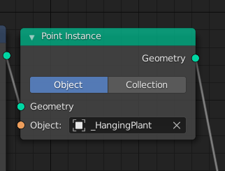
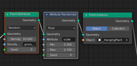
For that you add a Point Instance node between the Distribute and the Join Geometry nodes. This Instance node now is saying that instead of dots, let’s instance an object or collection on this plane. At first, the dots are going to disappear as well, but you just need to add your grass blade object that you created a couple of steps ago.

Nice! Now you’re probably seeing your grass blade distributed all over the plane. But it would be nice to get control over scale and rotation, for example. For that, add two Attribute Randomize nodes between the Distribute and the Instance nodes.
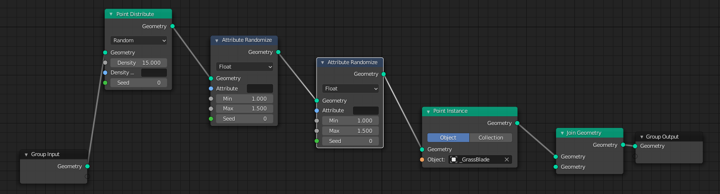
For each of the Attribute Randomize text fields, write scale and rotation. Keep the scale as Float and change the rotation to Vector. In the rotation min and max rotation, I set it to 0,0,0 because I want all of my grass blades facing forward. If you want Z rotation randomization, set the last max value to 360.
In the scale attribute, set the minimum and maximum scale that you want your grass to be randomized. Play around with the values!
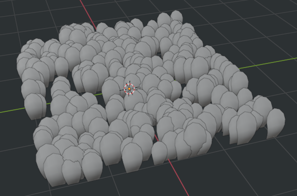
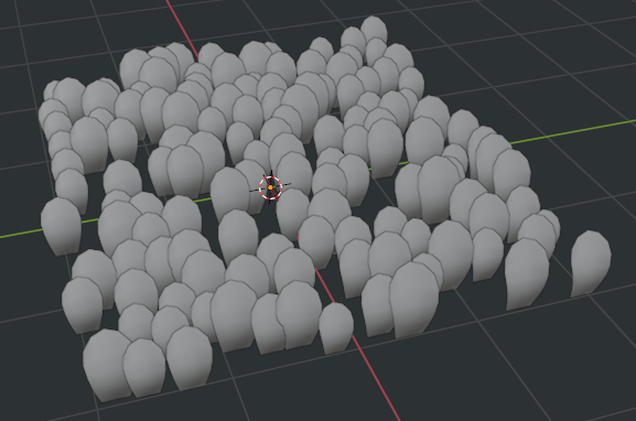
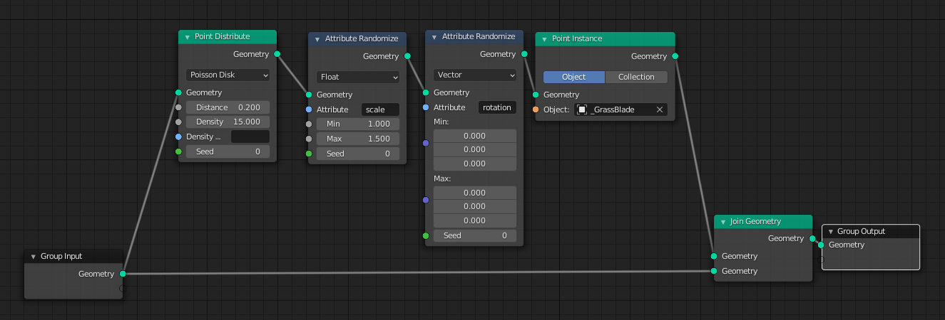
This looks quite nice, but you’ll notice that there’s a lot of overlap, especially if you go with higher density values. To counteract the overlap, we can try to change the distribution mode from Random to Poisson Disk.
When changing to this mode, you need to tweak the Density and Distance Min values to fit your needs.


If you want your plane to be visible again while using the scatter, just connect the Group Input geometry to the second Join Geometry socket.
And that’s how we scatter things around here!
8. Weight Painting
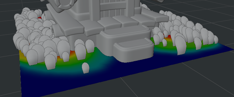
This is looking good but it would be nice if we could say where the grass is going to be scattered in this plane, so we can avoid it clipping through our front doorsteps, for example.
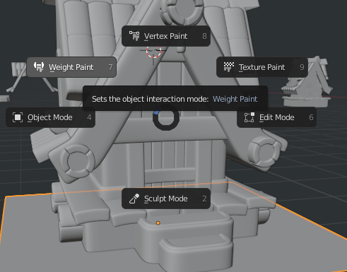
For that, we can work using Vertex Groups and Weight Paint!
Subdivide your plane a bit more, so you’ll have better control during the weight paint process.
Select your plane (in Object Mode) and go to the Object Data Properties tab on the right side of your screen. Under Vertex Groups press the + button and rename this vertex group to grass_density, for example, or anything that works better for you.
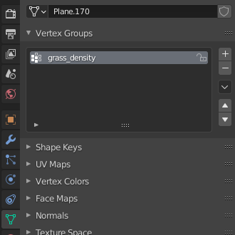
Now go back to your plane Geometry Node structure, and under the Point Distribute Density text field, type the vertex group you just created.

Your scattered grass is going to disappear because now the Distribute node is pointing at the vertex group, but this vertex group does not have any weight assigned for it.
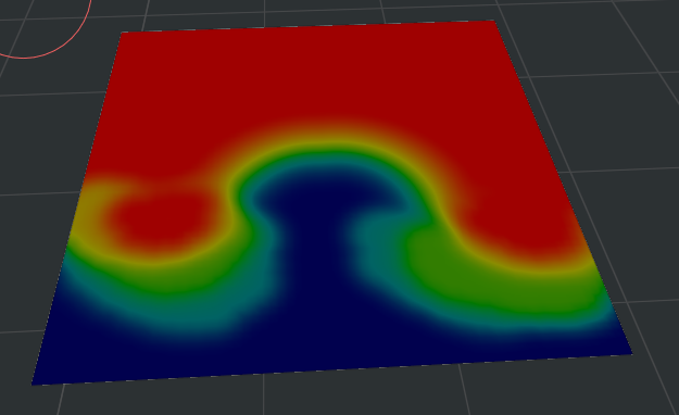
Let’s start to weight paint it. Select your plane, and press CTRL+TAB and select the Weight Paint mode.
Your plane immediately turns to blue which means that it has no weight in it.
In the top part of your viewport, you’ll see the Weight Paint brush settings. If you set the weight to 1, that means full weight assignment to your mesh. You can tweak your brush radius (using the brackets as in Photoshop) and paint the whole mesh or hold and left click-drag to perform a linear gradient paint.
Your plane will turn to red, which means fully weighted mesh and your grass is now being scattered again.


You can also set your weight to a value between 0 and 1 to fade your weight distribution better. Red means full weight, Blue means no weight and then the color blend in between these two values can help you to fade your weight.

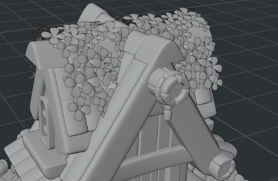
That’s how my weighted mesh looks. I removed the grass density from the front steps, and also created a smooth shade to my grass scattering.
Now we have some nice grass!
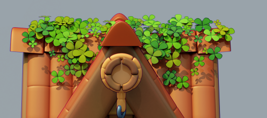
9. Hanging Nature
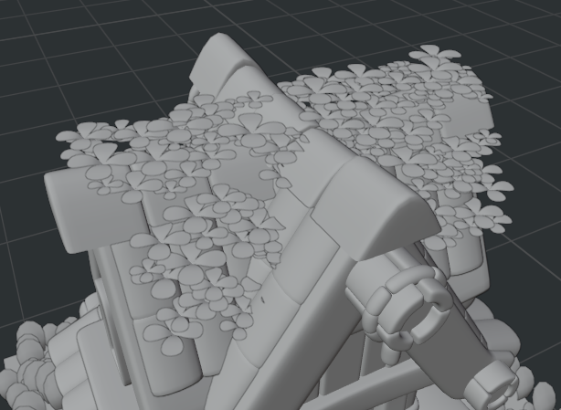
The next step is to reuse our grass scatter to create the hanging plants on our rooftop!
In Object mode, duplicate the ground plane we just created.
With this plane selected, go to the modifiers tab and disable the Edit Mode toggle.
Place this plane on your roof top, and shape it following the roof silhouette. Don’t worry about trying to make it perfect now—you can tweak it when you start to scatter the plants.

To model the clover asset that is going to be scattered, try the following steps:
- Create a plane.
- Inset (i) it twice.
- Select the edges marked in yellow and press V to rip them apart.
- Now select the entire outer loop marked in yellow. Then in the top part of your screen, switch the Pivot point selection to Individual Origins.
- Then scale them down and see what happens.
- Add a subdivision surface modifier (1 or 2 levels).
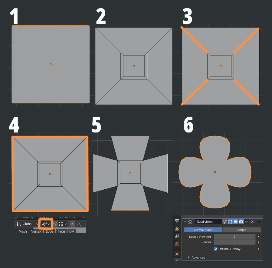
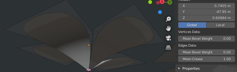
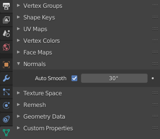
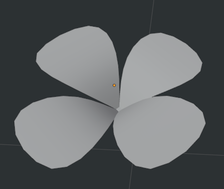
Select the center face of your clover and then move it down to shape it the way you want. With this face selected, set the Mean Crease to 1 for it. Also activate the Auto Smooth in the Object Data Properties.
Go back to the plane on your rooftop, and in the Geometry Node Editor click the number next to your Geonode system. This will safely duplicate this Geonodes structure, preserving the one you did for the grass. Name them properly so you know which one to use.
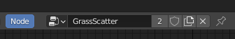
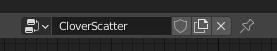
Make sure you’re in the CloverScatter one and start by replacing the grass blade object with the clover object you just created.
It works quite well already! But we want the plants to scatter pointing in the right direction across the mesh.
The quick way of doing it is to remove the Attribute Randomize node for rotation and it’ll follow your mesh direction quite nicely. If you select the rotation node and press CTRL+X, it’ll delete the node but preserve the connections.
Play around with your base mesh shape, weight paint, and scatter settings to get the results you are looking for!
Check back Friday to see the final installment of this tutorial.
About the Author
 Carlos Cavalcante, Game Artist in the mobile games industry and Blender enthusiast

It’s great to see another post from you!
Beautiful work!
Thanks for sharing your knowledge!