
About me
I’m Moran Goldstein—a designer, developer, and 3D generalist. I’m self-taught, and I’ve used almost every type of CAD over the years: 2D drafting, basic solids, nurbs, loft modeling, parametric 3D, and polygon mesh modeling.
I’ve been using Blender since version 2.68, and found it to be a very powerful modelling tool even then (even if it needed a few plug-ins to give it a leg up at the time). Today it’s one of the most powerful modelling tools I know of.
Because my job requirements keep changing, I sometimes take breaks from rendering for long periods of time, which was the case with this model. It’s the first for-display piece I’ve done in 4 years (with maybe one or two exceptions of prototype displays).
Before working on this piece, I was doing modeling for 3D printing (mainly FDM) for a few years.

Learn more on qarnot.com.
Motivation
I wanted to get back into rendering/display as a result of seeing what real-time engines can do these days. I saw remarkable videos made using UE4 and Unity, and when I saw what could be done using EEVEE, I knew I had to try it out.
As a result of this being my first EEVEE render (or any real-time render), it has many flaws. I managed to obfuscate some of them by adding a lot of detail and motion. The main problem is that I was still thinking in full raytracing terms, as opposed to optimizing for a rasterizer with screen space reflections.
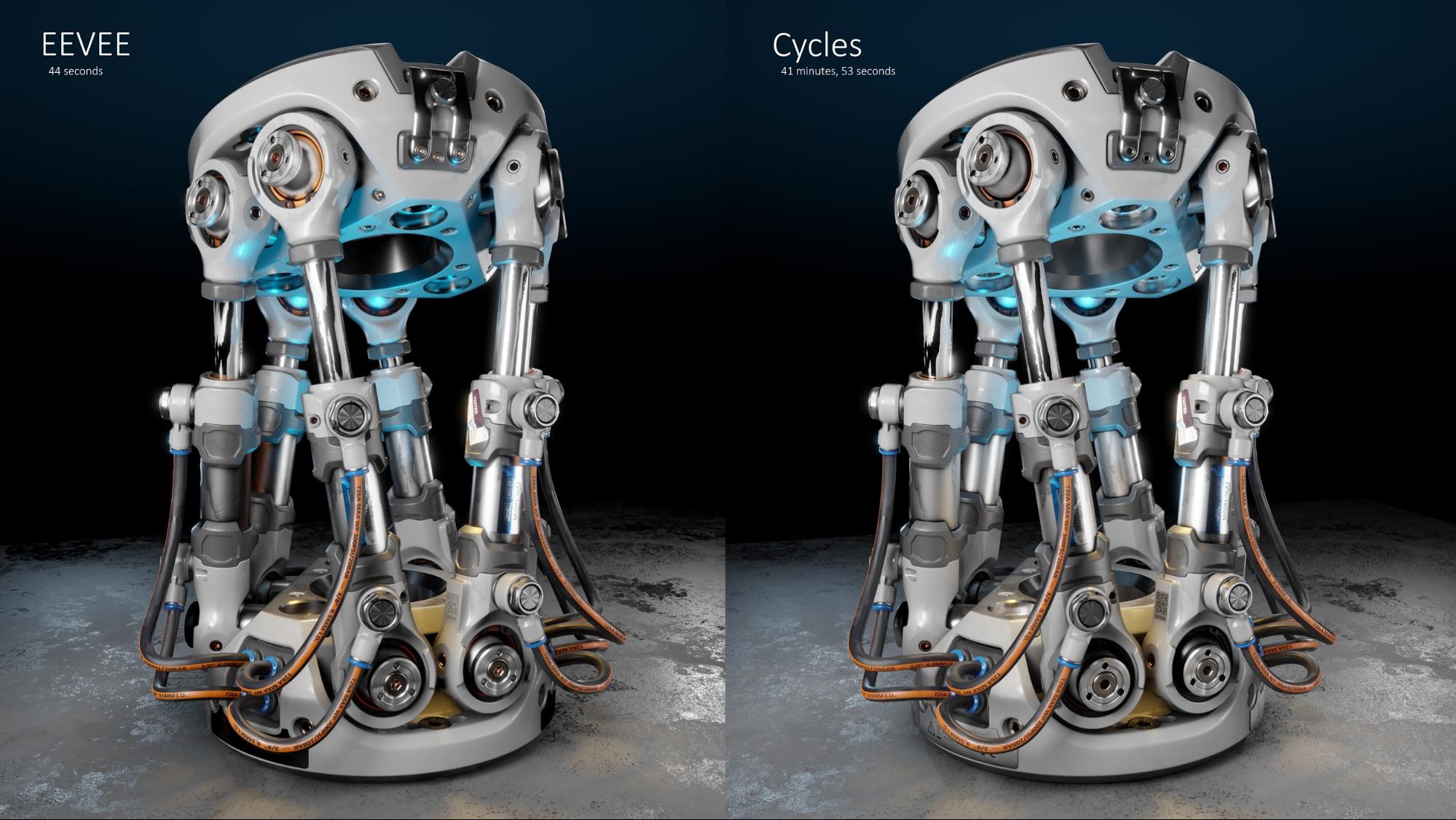
I do find it interesting that, by the end, the EEVEE render and the cycles render were almost the same:
The Mechanism
The Stewart Platform is a 6 degrees-of-freedom mechanism that uses 6 pistons to allow full range of motion. By adjusting the pistons (which can be substituted by any linear actuator), you can move the platform in the X, Y, and Z directions, as well as rotate it on three axes—pitch, roll, and yaw.
Depending on the hardware used to construct the platform, it can either be used as a backlash-tolerant approximation tool, or as a very rigid and precise location mechanism.
Goals
I had several objectives when making this piece:
- Learn to use EEVEE, specifically the tricks and hacks that best allow it to “fake” a raytraced render appearance.
- Try out different stylized, non-photoreal shading techniques.
- Test the realistic number of faces that EEVEE can handle and still run in, practically, real time. This is heavily affected by shader complexity and enabled features.
- Use as much procedural shading as possible.
Additionally, I imposed the following limitations:
- Bitmaps are only allowed for labeling, everything else must be procedural. In the end there were two exceptions—the concrete ground material, and one scratches texture.
- No UV unwrapping allowed, and no vertex painting. I thought this would prevent me from leaning on baking to achieve certain effects, though by the end it was a somewhat arbitrary handicap.
While there are many things I’d do differently if I made it again today (at the time of writing it’s 2 months after I published the work), there are a few techniques that continue to serve me well:
Condensation
When you have larger smooth surfaces, it’s common these days to scuff them up and make them feel used. This is very effective, but it wouldn’t apply if you’re presenting something that should appear brand new, or just well-maintained.
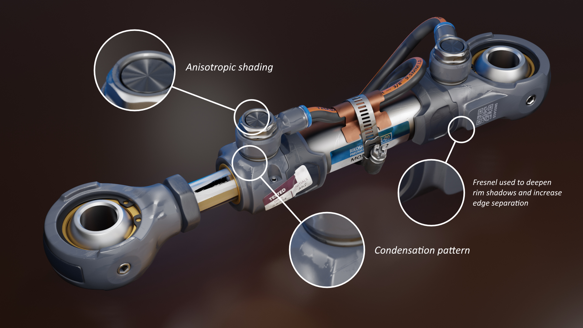
If the surface you’re working on is smooth and non-porous, it’s likely that thin films of fluid will be more apparent, as well as condensation patterns. A visible condensation pattern does not mean that the surface is wet—remember what a car looks like a few hours after the rain. The water dries up, but some of the sediments in the water remains on the car.
If you look at photos of machine tools, it’s not likely that they were kept out in the rain, but it is likely that they’re regularly lubricated. This could either be lubricant applied to joints (which will sometimes spill onto adjacent surfaces), or any substance applied to surfaces to prevent rust from forming (like WD-40). Whatever the case, the variability in roughness will be apparent on smooth surfaces, whether they’re metallic or not.
Here are two node setups that will produce patterns similar to this effect:


The first setup is faster, but a bit less convincing. The second is slower but appears more like what you’d expect to see in real life.
Remember that, as with almost any procedural shader, you don’t want it to be the only “actor” affecting what you see. We can very easily pick up on fake patterns. However, in combination with other shading techniques, it can make surfaces appear more layered:

Since these patterns typically describe the fluids (or very small particles) that are layered on top of the actual material, they’re also a good candidate to be defined using clearcoat. I’ve had mixed results using them as clearcoat (and/or clearcoat roughness), it really depends on the type of material that they’re layered onto.
Outlining
This method does not derive from physical properties, it’s a stylized one. That said, if you have many similar materials applied to different objects which are close to one another, it’s sometimes difficult to see when one stops and another begins. In real life, our eyes will help us separate objects by depth. Even with just one eye you’d be able to pick up on very subtle depth of field.
To compensate for this, I sometimes use the fresnel node to fake an outline. The object on the right is shaded regularly, and the one of the left uses the fresnel node to create a very thin outline:
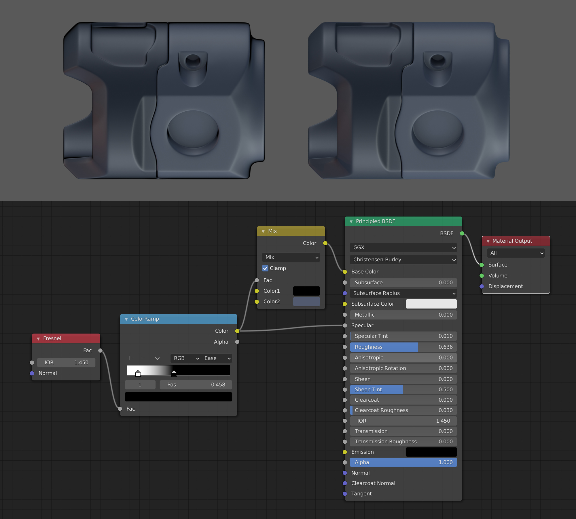
You can lean into this effect more heavily if it’s a stylized render, but if it’s supposed to look somewhat realistic you should keep it to a minimum. Just a slight darkening of the perimeter should be enough to help separate objects from one another.
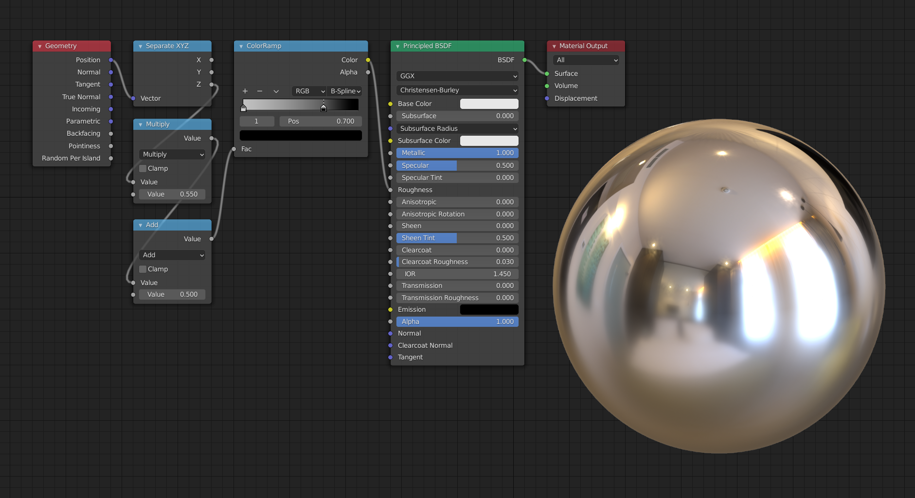
Anisotropic Shading
The EEVEE rendering engine does not yet support anisotropic shading. However, since anisotropic reflection is the result of the topological characteristics of the object, you can actually trick EEVEE to produce them by mimicking those topologies.
When a surface is polished radially, like the bottom of a pan, it creates a large number of concentric grooves -- like a vinyl record. To replicate this, create a node setup that will generate repeating concentric circles, starting from a point in the center:
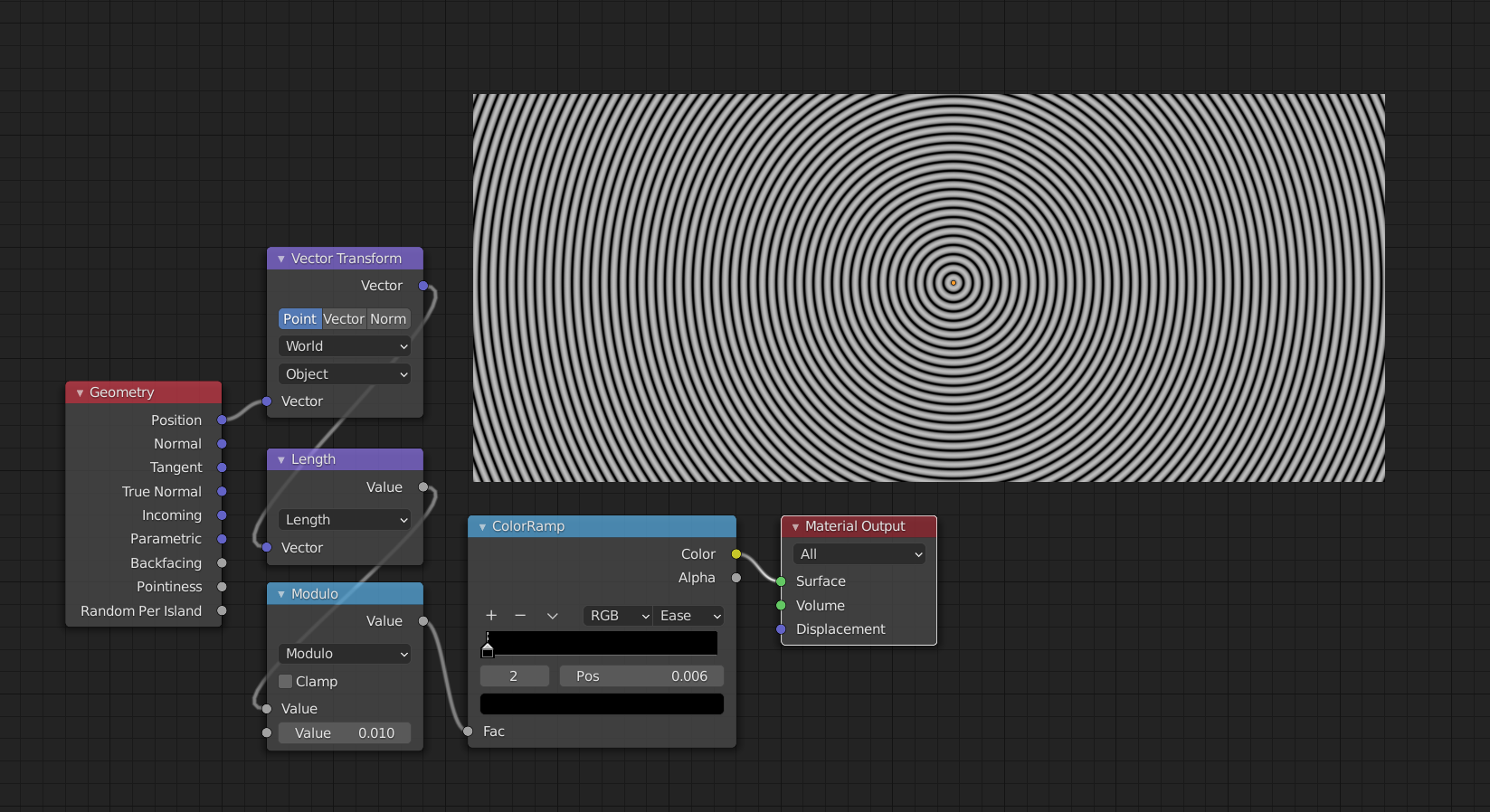
Then, use the bump node in order to turn them into normals which you can plug into the normal input:

Depending on the surface you’re trying to make, I find it useful to also plug it into the roughness input, so that the valleys are rougher than the peaks.
Mistakes and Pitfalls
As I mentioned above, there are many things I’d do differently if I were to make this now.
The primary mistake I made was placing any artificial constraints on the work. For example, the pointiness node isn’t currently available for EEVEE, but you can bake it in Cycles. This does require you to UV-unwrap your parts, but if pointiness is all you need then it doesn’t have to be an especially optimized unwrapping.
EEVEE also lets you get away with floaters more easily. I only used one in this model—the QR code—but I could have gotten away with more of them, including non-flat floaters and normal-mapped ones.
While procedural textures/shaders are great, there are certain effects where you’re better off using bitmaps. Mind you, this doesn’t mean you can’t use a procedural method to make these bitmaps.
I’ve seen node setups that generate fairly convincing scratches, but they were exceptionally heavy. In cases like those, I’d either bake the shader output into a bitmap, or look for existing scratch textures that I could use.
Additionally, scratches contain very fine details. I think I used 2k scratch textures, where I should have used at least 4k.
The geometry node gives you access to global location information. This can be used to transition a property from one value at a lower altitude to another value at a higher altitude. Here’s an example of making an object rougher on the bottom and shinier on the top:
If you’re designing a larger structure, you can have more dirt accumulate at the bottom compared to the top. You can also use it to artificially make an object darker near the bottom, though that would fit a more stylized render.
About the Author
 Moran Goldstein, Freelance 3D generalist, hard-surface modeler, and industrial designer.
1 Comment
Nice work Moran! You are absolutely right about the wear patterns on well maintained machines.
So much lazy material creation without real world reference leads to rusty mechanisms with fingerprints everywhere. This is very helpful and thanks for sharing!