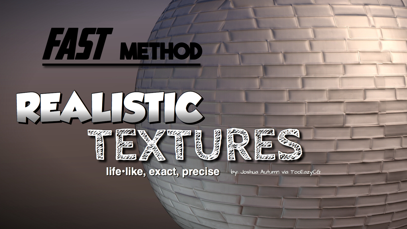
The FAST method for creating Realistic Textures
JoshuaAutumn writes:
Having realistic materials is like the golden rule to making photorealistic scenes in 3D modeling. Without good materials, the scene (or meshes) won’t look real. Of course there are a few methods on doing this in Blender, for example, messing around in the material nodes, or photo scanning surfaces, etc. But now that Blender has evolved throughout the years, the software has improved a lot, extending limits, improving features, and making methods way easier. For example, there is now an easier and quicker way on creating realistic materials in Blender. Although this method isn’t 100% the best way, it is still a very good way! If it wasn’t a good method, I wouldn’t have made a tutorial on it. Watch this 5 minute tutorial to learn :)
The normal map is in the wrong format in the thumbnail image.
Something I’ve seen many times but never fully got the reason for: Why does the normal map have to be set to non-color data for the colorspace? I thought the purpose of a normal map was to have the blue, red and green color channels all present for greater precision, wouldn’t the non-color data conversion change the map to greyscale and thereby lose the extra precision that make normal maps more accurate than simple height/bumpmaps?
A normal map is made up of three separate greyscale channels X,Y & Z. It’s an elegant ‘hack’ to have a normal map use an image format as a transfer format. Normal maps could be some sort of specific, arbitrary file format created specifically to hold normal information but we wouldn’t be able to browse them and see what each one was representing or see any obvious errors in them until we applied them to geometry.
I am unclear though how an 8bit greyscale channel (0 to 255 values), is used to represent 360 possible angles per channel. Someone more technical can chime in there.
I’m not sure if that answers your question but if the normal map was treated as colour data it loses precision (only 255 degrees of angle per X,Y or Z channel)?
Sounds like something hidden in the file format, perhaps it makes use of compression channel information to get the full range of 360 values per channel. That could also be why some picture formats don’t work well for storing normal maps. Either way, that does makes some more sense now.
Just let 128-255 mean negative and map it to 0-128 and 0-127 just be positive. Z might just range from 0-255 since you normally don’t need negative Z.
With this you can now have half a sphere.
There is nothing really “magical” about the number 360. You could just as easily represent a full arc with, say 100 values. You may have to multiply it by 3.6 when giving it to someone who expects 360 degrees in a circle, but as long as you know how many there should be, there’s nothing stopping you from making 50° protractors etc.
That said, I think it’s easier to think of a normal map as storing a normalized, 3D vector rather than some kind of angle. That is, three values between -1 and +1 which always add up to +1.
Each channel (R, G, B) of a given pixel represents some value in the X, Y, and Z axis. Since negative values usually aren’t acceptable in image formats, they are remapped to 0..1 instead.
In a tangent-space normal map (the most common kind), these X Y and Z values represent an offset from the surface “normal” (those blue lines always perpendicular to the surface which can be visualized by enabling the face icon under “normals” in 3D view > Properties region > Mesh display while in edit mode). Hence the name “normal map”.
Non-color data doesn’t mean it’s converted to grayscale, but that it’s not a color map, like a picture or hand painted texture.
Computer displays and televisions apply a gamma of 2.2 in the whole screen. So a value of 0.5 (between 0 and 1) is not the doubled intensity of 0.5 (which how the light naturally react). To us it look more natural, but for computing lighting in a 3D scene this is bad.
All the image that we generally use (JPG,PNG) have got colors encoded with this gamma of 2.2, even a camera took the photo and apply this gamma transform so the picture look natural. But this change all the color informations that as been taken from nature.
So blender inverse this gamma value of images textures before doing a render, and set it back at display time. So the rendering calculations are more natural.
Setting images to non-color data tells blender not to do so, and use the color information in the image directly.
This is related to linear workflow in blender and maybe a google search can explain it better than I.
@AROBOTTOM : I’m not expert in normal maps, but that’s seem more logical that the degree range goes from 0° to 180° so we may be safe with the 255 color per channels. But maybe with 16bits images there are more informations leading to a finer result. I never got issue tho.
In Blender, setting an image node to “non-color data” means your color/gamma correction won’t be applied to it. If set to “Color data”, they will.
For diffuse maps and other things adding visible color to your scene, you want this. For images that are being used for their numerical values, you don’t want color correction settings to skew them, so you set them to “non color data”.
Choosing “non-color” doesn’t make the image greyscale; instead I believe it reads the image “as is” without any sRGB gamma fiddling.
You can see this in the render preview if you connect the non-color texture directly to a color output, rather than the normals.
Pro surfacing artist hate him!!!
Sorry, ignore my post. I didn’t reach the grey scale part :-(
I remembered having this somewhere in my code (I think it originally came from somewhere on the internet though) :
I think grey scale might just be a bump map. You can then convert it as follows. take the pixel in x+1 and x-1 and Y+1 and y-1. Create two vectors from these one in the X-Z direction and one in the Y-Z direction. The Z height is determined by how much the grey scale value differs.
Then take the cross product of the two vectors so you get one that is perpendicular to both. And that is your normal vector.
std::unique_ptr MImage::NormalMap( double OnePixelDistance, bool IncludeHeight )
{
if( Width < 2 || Height < 2 || !Rgb )
{
return std::unique_ptr( new MImage );
}
double TwoPixelDistance = 2.0 * OnePixelDistance;
std::unique_ptr Result( new MImage( Width, Height ) );
vector HsvImage( Width * Height );
CRgb *RgbStart = &Rgb[ 0 ];
CRgb *RgbEnd = &Rgb[ 0 ] + Height * Width;
vector::iterator HsvIter = HsvImage.begin();
for( CRgb *RgbPtr = RgbStart; RgbPtr != &*RgbEnd; ++RgbPtr, ++HsvIter )
{
*HsvIter = *RgbPtr;
}
// GO through the luminance in the X direction to create the X = R value as float (we abuse another HSV array
vector NormalAsFloat( Width * Height );
// TODO: Edges (either take the other side to make it seamless or just the use the first and second
for( long Y = 0; Y < Height; ++Y )
{
for( long X = 0; X < Width; ++X )
{
long XMin1 = X – 1;
long XPlus1 = X + 1;
long YMin1 = Y – 1;
long YPlus1 = Y + 1;
if( XMin1 < 0 )
{
XMin1 = Width – 1;
}
if( YMin1 = Width )
{
XPlus1 = 0;
}
if( YPlus1 >= Height )
{
YPlus1 = 0;
}
KDVectorT Horizontal( TwoPixelDistance, 0.0, HsvImage[ Y * Width + XMin1 ].V – HsvImage[ Y * Width + XPlus1 ].V );
KDVectorT Vertical ( 0.0, TwoPixelDistance, HsvImage[ YMin1 * Width + X ].V – HsvImage[ YPlus1 * Width + X ].V );
Horizontal.Normalize();
Vertical.Normalize ();
KDVectorT Normal = Horizontal.Cross( Vertical );
long Location = Y * Width + X;
CRgb& Rgb = ( *Result )[ Location ];
Rgb.rgbRed = static_cast( std::min( std::max( Normal[ 0 ] * 128.0 + 127.0, 0.0 ), 255.0 ) );
Rgb.rgbGreen = static_cast( std::min( std::max( Normal[ 1 ] * 128.0 + 127.0, 0.0 ), 255.0 ) );
Rgb.rgbBlue = static_cast( std::min( std::max( Normal[ 2 ] * 255.0, 0.0 ), 255.0 ) );
Rgb.rgbAlpha = IncludeHeight ? static_cast( std::min( std::max( HsvImage[ Location ].V * 255.0, 0.0 ), 255.0 ) ) : 255.0;
}
}
CrazyBump is not free software as far as I know…